MG-Rover.org Forums banner

Gear stick sequential indicator

9.6K views 66 replies 18 participants last post by  Alibro  
#1 · (Edited)
Today i unpacked my Mike Satur Slick Shift gear change kit, to give me better control of gear changing in my Trophy 160...

I have chosen to not use the original gear change knob, in fitting the kit, because i see the means to have sequential gear change indication in the gear knob...

I see this type of gear knob as having the basic means to do it..

http://www.ebay.co.uk/itm/RACE-CHROME-STICK-GEAR-SHIFT-KNOB-SHIFTER-LED-BLUE-/221119324177

Image


This gear knob only has one led... but has the provision to allow more...

i want six... one for each gear... and all lit when the gearstick is in neutral...

folks will say, why not have that indication in the dash...?

i dont want to change the dash.. i like it as it is...

i see that i can have gear change indication and neutral.. just by changing the gear knob ...

what i want... is to have one led for each gear change - lit, and all on when in neutral.

i want blue, its a Trophy Blue MGF..

but one could choose any colour.

i immediately see the problem of where and how to hide six wires, and power ( seven in total ) so that they are not visible on the gear shaft...

and the method needed to carry out the switching... either contact switches or proximity switches... ( ive not decided yet.. )

The effect i want is this...:

When a gear is engaged the gear number is lit... just that gear..

When in Neutral all six leds are lit..

The effect is a bright flash as one changes gear... since the crossover from one gear to another is momentary... but through neutral

when one sits with the gears in neutral.. all six leds are lit...

i think i need to use very fine lacquered wire, maybe from an old relay coil, to enable hiding the wires from the leds in the knob.. as they travel down the gear shaft...

because my car is Trophy Blue... i could use a discreet blue ( or black ) sleeve to do that...

some folks think that a dash indicator is what they want... its not what i want.. so dont tell me its better... or easier.. or preferred , i want the indicator in the gear knob..

i just share this topic on how i do it..

and... i hope folks give me some ideas to consider to achieve it...
 
#6 ·
Might it not be wise to buy two? One is the prototype, the second the refined end product? Maybe even three?


Re hiding the wires; How about using a nicely sewn leather sheath over the shift column. Another thought is to house the wires in a thin tube and fix it in a spiral fashion from top to bottom?


Val.
 
#5 ·
Telephone cable is extremely strong... but.. it has a sleeve... standard telephone cable with its integral sleeve is too obtrusive... i think.. i want thin and tiny.. its easier to hide..

?

a lacquered wire wont like flexing at a curve.. it will break the lacquer and therfore leave the wire open to short, or breaking in two..#

thats something i need to solve.. flexibility and insulation..

hmm..

i need to have a wire that is insulated, of small dimension that can withstand flexing...

else.. i need to remove the flexing... as a consideration..

or.. solve the flexibility causing breaking.. ptfe wire?


its an option.. remove the flexing, removes the problem of flexing..

else remove the flexing of the insulation as a consequence... ptfe?
 
#9 ·
My thoughts are:
Red led for reverse, yellow for neutral.

Rotary encoders or potentiometers on each of the shifter's axis with a little bit of logic on a chip.
i.e. Longnitudinal axis Position 1 + Lateral axis Position 1 = 1st
Longnitudinal axis position 3 + Lateral axis Position 1 = 2nd
Longitudinal axis Position 1 + Lateral axis Position 2 = 3rd
Longnitudinal axis position 3 + Lateral axis Position 2 = 4th
Longitudinal axis Position 1 + Lateral axis Position 3 = 5th
and
Longnitudial axis Position 3 and lateral axis Position 3 = Reverse.
and finally
Longnitudinal Axis Position 2 + Lateral Axis Position 2 = Neutral

Or resistance level 1, 2, 3 for pots.


Once you have it working i'll follow on with a dash or heads up display one.
 
#11 ·
thank you blackoctagon... i need to re read your post several times before i fully understand it.. since i just see the position of the stick as a visual image in my head.. not a mathematical theory..

i dont mean that as derogatory... i just have difficulty seeing longitudinal...

i see this way and that way..:)
 
#14 ·
nah, i understand what you meant DD, i dont have an issue... dont be sorry.. its a valuable input.. but i sense , that even stripped of the outer casing , telephone cable isnt up to constant flex... i need either better insulation or more flexible wire, or both.

an impossibility maybe.. so i need to consider the result of failure and try and take care of it.. broken wire will cause a short.. fit a fuse..

broken insulation will cause a short.... fit a fuse..

i want a protected circuit... leds are low current... i dont know the exact current draw of 6 leds yet.. that can do the job.. but the fuse must be close and quick action.. and it must be accessible.. somewhere near the battery.. or the under steering wheel fuse box.. not buried in the gear stick casing.

one can chocolate block.., so that the flexing wires to the leds dont need to travel far, before more stable wires take over..

that means one could make up a complete replacement of the gear knob assembly, as Val has suggested.. for easier failure replacement..

live with the failure disadvantage.. and make the replacement easier..

i am still biased ptfe.. but i might start with telephone wire, or lacquered coil wire.. to test my assumption..

i am happy to be proved wrong.. since the cheaper the better solution..
 
#15 ·
Yeah, Thank Peter, as an ex wireman, i was pretty confident that ptfe was what i wanted.. you confirm that.

i see a simple relay being the only electronics needed..

a 6 Form A ( N/O) Relay will do it..

Image


when the gear stick is in neutral.. the relay energises, and closes its switches....

so all i need is a twelve volt 6 Form A ( N/O ) relay, a 1 or 2 amp fuse, 6 leds configured for 12v, and 7 proximity switches (or something ...) and some ptfe wire..

?

its not the bits thats going be hard to get... its getting the switches to work..

the relay dont need to be anywhere near the knob or shaft... it can sit somewhere else easy to get to.. with the fuse..
 
#16 ·
I'm a bit surprised no-one has mentioned the possibility of using the steppy gear indicator in the dash. (I've no idea how that works, but perhaps blackoctagon has worked that out?) That could be instead of or in addition to LEDs in the knob; but it would require the same sort of detection arrangement.
 
#17 ·
i understand... but as ive posted , i am not venturing changing the dash..

i dont need to or want to..


the wiring diagram ive shown.. needs a little bit of knowledge to understand..

since the six relay switches, only operate and allow all the leds to be linked when the coil is powered... though my diagram is a little misleading because it shows the blue link connected to black at each led.. thats just for simplicity.. because i just scratched the pic together just now..

:)
 
#19 · (Edited)
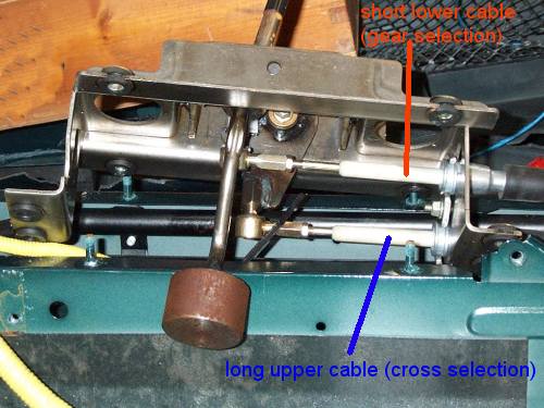
looking at this pic..

Image


i think the switching needs to be either magnetic reed switching or proximity switching.. of a simliar kind...?

the shafts determine position for gear selection... and attaching magnets to them is my first thought... then the position of the magnets, operate reed switches? i havent seen a pic yet showing the shaft positions, for each gear and neutral.. and it may be that the gear box end is the place best suited to switch location... in which case the relay could be mounted in the boot... in a closed labelled box.. and then just a multicore cable to the led junction point where ptfe wire takes over..

ideas anyone..

i`m venturing maplins store now, to have a peruse at relays and switches and leds :)
 
#20 ·
I can understand this for geekness/gadget factor and personal taste, but I don't understand the work/gain ratio involved for actual practical use.

This must be in the same box as the push start buttons, good for show but no practical use. ;)

It will be interesting to watch though.

You may find reed switches might not be to good in a steel cage and microswitches prone to wear/failure.

You might even consider using a low voltage inverter with coils set at each gear location with the secondaries positioned on the bottom of the stick. As you select a gear the two coils will line up enough to give an emf in the secondary which will provide enough current to light the corresponding LED. In this way you would have no moving parts and no cable connection to the stick itself.
 
#21 ·
No choice for me but to have a push button starter.. and stop.. As I've thrown the steering barrel away.. And the key..

I can totally understand where Incony is coming from.. Set yourself a challenge.. And conquer it..

Similar (but smaller scale) to climbing a mountain.. What's the point? For the view? The exercise?..

Why do people swim the channel? We have a train and various boats.. No need to swim..

Keep it up Incony.. Watching this with interest
 
#22 · (Edited)
Thank you CJJ. that is an interesting idea.... : Quote
"You might even consider using a low voltage inverter with coils set at each gear location with the secondaries positioned on the bottom of the stick. As you select a gear the two coils will line up enough to give an emf in the secondary which will provide enough current to light the corresponding LED. In this way you would have no moving parts and no cable connection to the stick itself."

a coil needs its wires connecting to something.. and the leds are in the gear knob..

why are the leds in the gear knob? ... because thats where i want them... :)

i use my working mgf`s as a test bed for methods, i might want to use in a Vectis..

gear selection indication, as cheap n cheerful as possible, but robust and without electronics where possible.. and without changing the dash.. suits me this mo..

one doesnt have to go for a walk... or wander down the garden... but sometimes the work/ gain improves how one deals with things... since it uses the mind...:) problem solvers are like that... if they dont have a problem, they may well invent one and solve it... and solutions are not fixes... its something one has no evidence or traceability for.. until one does it..

if someone else has done it... then i want to see it... so i can compare thought with thought..

why do folks do crossword puzzles?
 
#23 · (Edited)
well i visited my local maplins and they dint have any blue leds in stock.. every colour but blue...

and no more than 2 form relays in stock... no specific proximity switches...

i visited Halfrauds... close to Maplin in Kings Lynn... went in and went out...

i will have to use the web.. i know ive found at least one supplier of 6 Form A Relays.. and this mo at christmas, everyone is selling blue led multifunction christmas lights... so opportunity exists.. :)
 
#24 ·
excellent.. ty.. g0rsq, removing the relay is a plus...

using 1N4002 diodes instead, is more robust..

and cheaper...
:)

sometimes ones mind doesnt see the obvious.. especially as one gets old...

its why i share topics.. since feedback gives one everything..

:)

cheers mate.. happy christmas..:)
 
#25 ·
Thanks to Peters interest, i am not looking for a 6 Form A Relay now.. IN4002 diodes or similar are easily available, and using them removes moving parts.. a big plus.. ;) relays fail... they suck compared with diodes for led control.

i still need to figure the switch operation.. and so far i see either the gear stick connecting shafts or the gearbox, as the place the switches can be made to work reliably..

i dont favour the gearbox, because its open to the elements.. but if its a more reliable way.. then so it must be..

i need to get my f up on the four poster and take some pics i think.. the position of things in gear and neutral.
 
#27 ·
ok.. i like the idea.. but i need something to see.. to consider.. can you make a pic and post... crude is ok.. its the idea i need to see...

in one post peter changed my whole conception of what was needed? do you think i need this in favour of what i see as an improvement?

tell me.. show me.. i will go with it if.. its better... and that is your judgement.. so you want me to believe.. convert me.. :)
#
 
#28 ·
ok.. i like the idea.. but i need something to see.. to consider.. can you make a pic and post... crude is ok.. its the idea i need to see...

in one post peter changed my whole conception of what was needed? do you think i need this in favour of what i see as an improvement?

tell me.. show me.. i will go with it if.. its better... and that is your judgement.. so you want me to believe.. convert me.. :)
#
Something like this

Image
 

Attachments

#29 · (Edited)
there is also the slight movement of the gear stick, even when the gear is engaged to consider.. there is range window that a proximity switch can cope with.. but i think a coil might not.. as gOrsq suggests..

an opto switch wont be my choice, because of contamination weak point,

a reed switch needs a magnet, and the magnet will attract contamination too..

a micro switch is an option... i know that micro switches operate in pretty hostile environments.. i service them on overhead travelling crane hoist limit switches, that get smothered inches deep in weld dust.. but they would need the range window problem taken out, too.. since slight movement or play, can be the difference to a micro switch being open or closed..

one plus for a reed switch is that the gear stick mechanism is largely aluminium.. and less likely to attract magnetic contamination... grease and oil wont bother it either.. neither will dirt...

i see contamination effects and range window effectiveness as being important things for long term reliability..

so a field effect window wins for me this mo... since the range window is good..

if coils can do that and cope with slight contamination.. and range effect.. then i still see the reliable mounting of the coils as being important ...and not as easy as switches... a reed switch is pretty simple to mount..

BUT.. if CJJ , you think its a good solution, and now i understand your idea , since the pic is usefull to visualize it..., then maybe its a topic on its own...

gOrsq... you know how electronic vernier gauges work?
they use a linear moving coupling to determine position.. is there something like that idea that could work? is that what you see as a transducer?

ie how about three potentiometers used as a voltage output - sum total for each gear and neutral?

that would be possible, since the mechanism of the stick uses rotary movement.. three planes...

potentiometers are good - being sealed they will avoid contamination.. even though they wont like oil contamination.. or grease..

mounting them would be difficult... and it would need electronics.. a computation..

i like the potentiometer idea... if you gOrsq and CJJ can help with the electronics needed
 
#31 ·
That looks well cool, Ianto Wraight... i am sorely tempted... :) its above budget , but i have to say i like the characters...

i need to know more about how it operates and fits.. since i think ÂŁ150 isnt the whole story..

?

i will email them to discover more.. tomorrow.. not least how will it see the gear position.. so far its the most difficult thing to resolve..
 
#33 ·
Don't want to add more confusion but you could do what some after market motorcycle displays do and monitor rpm and road speed, simple maths then gives you what gear you are in (unless you are at a standstill with the clutch in :)), no need for switches at all then.
 
#34 ·
i understand Paul Tim.. thank you for the input... and yes ive considered that, though not posted the option.. rpm and speed mean you are in a particular gear... but you could be going in reverse.. motorcycles dont do that..

?
 
#35 ·
Thanks, back to your original idea, if I had to implement it I'd probably go for a two part solution.
Sensor PCB/Display with 6 surface mount LED's and a 8 pin microchip microcontroller or similar which talks to a sender unit mounted near the gear shift via 2 wires (+12V and signal, use the shaft as the 0V return) that minimises the wiring.
Sender unit using switches or hall effect sensors+magnets (these should eliminate moving wiring) which are encoded by another microcontroller and the resultant serial output is fed to the display PCB. This should allow some calibration of switching thresholds to allow for shaft position variation.

Not a simple solution but an interesting engineering challenge, might get some HNC students to do it as a project next year to see if it works!

Good luck with the diodes/relays, be interesting to see how it works
 
#36 ·
i will get more info on the link you shared Paul Tim.. since my OP..- my wish.. is for the gear indication to be in the knob.. i dont want to change the dash..

the other option possible though, is can i use the existing milometer display to show gear position. by button push..

that would open the opportunity to use the existing digital display to do more?