

One day a man came to visit me and said that he was intending to turbocharge a TF and that he wanted to use the VVC head, and asked me if I could help by modifying the combustion chambers and ports. I said yes and I did a few simulations of some ideas I had in my old employment and asked if he'd like them done, and he agreed.
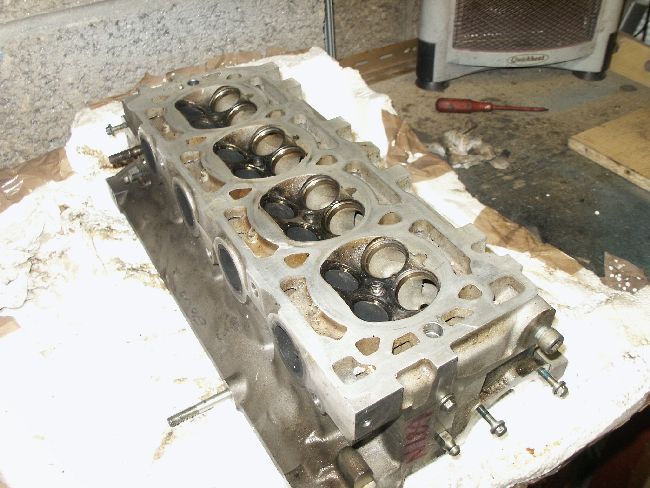
The head was a good condition vvc 160 unit with relatively poor cast features but good guide to valve cocentricity and no scary features.
As it was going on a pressure charged engine I decided to go to town on the ports and combustion chamber, match the manifolds, both inlet and exhaust (sometimes controversial), but to watch my hotspots and leave metal to transfer heat away from the valves.
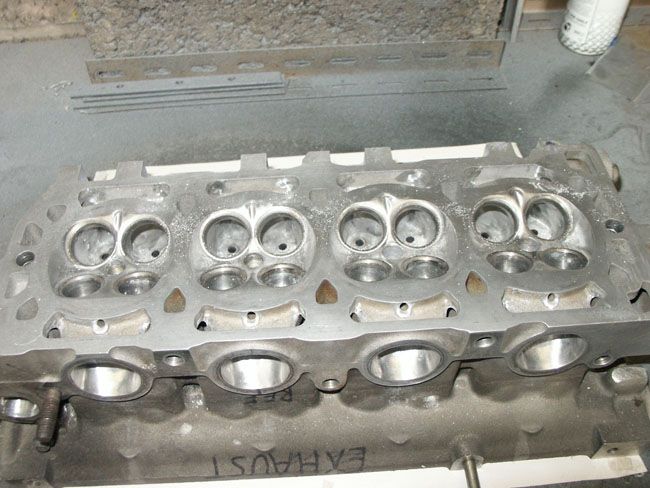
The head started like this:
![Image]()
The first job I attended to was to clean up the water passages. I do not have photos of this, but they look good now.
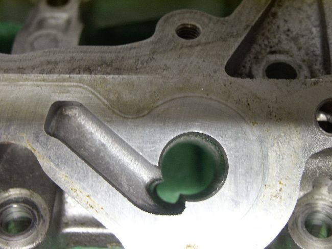
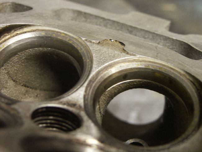
The second job was to clean up the casting near the VVC hydraulic control unit (HCU) rack
This photo shows the HCU rack boss after the casting flash had been removed:
![Image]()
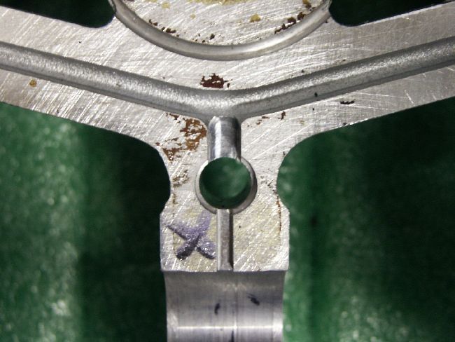
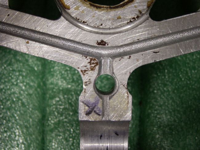
I then radiused the cam ladder oilways that flow around the ladder bolts as the passages are quite narrow and you don't want to lose unnecessary oil pressure to the cam bearings. If you don't quite follow then think of a bellmouth and how it prevents losses to turbulence and recirculation.
The first picture shoes standard and the second after radiusing -
![Image]()
![Image]()
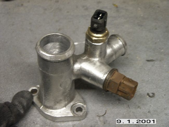
I then used rotary sanding tools to clean up the coolant passage elbow, and thought that the Magpies would like something shiny, so I cleaned off the surface corrosion
![Image]()
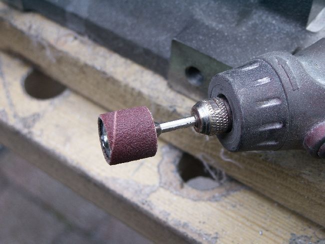
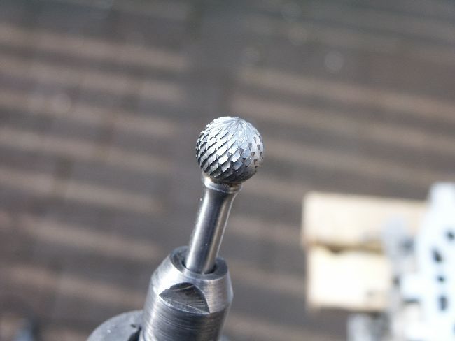
I use a Makita die grinder (240v) with a home-made variable speed control for heavy cuts and large diameters, but I also use these kinds of tools when I have a nice soft aluminium head to alter, especially for combustion chambers:
![Image]()
![Image]()
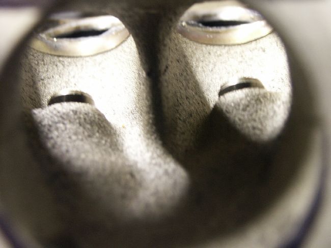
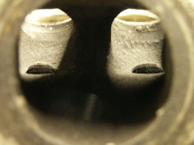
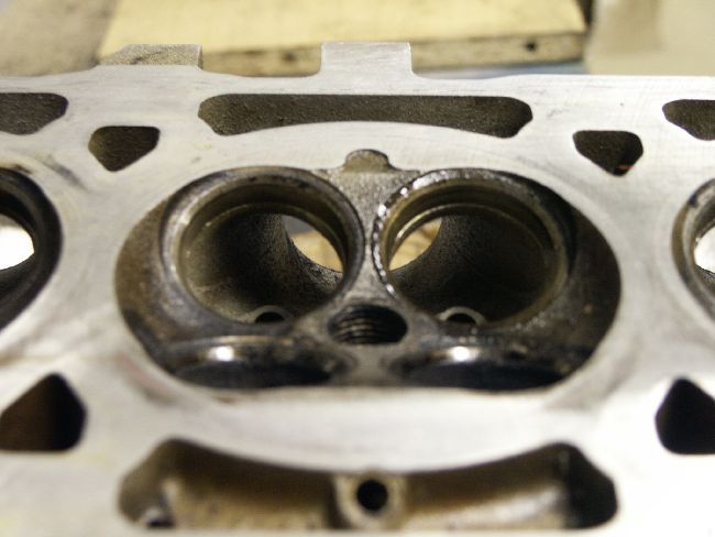
These are the inlet ports, as viewed from the manifold.
You can see quite a high surface roughness, a rather nasty casting line on the web between the ports, the seats are not well aligned with the port walls, and the web is quite thick leading to a rather blunt bifrucation into each valve from the port entrance.
![Image]()
The was simply cleaned up, the shape of the valve guide bosses were smoothed out but not completely removed as it uses a cut down valve stem guide and I wanted to retain some metal to dump heat to. Conventional wisdom suggests that the valve guide boss should be removed to prevent a partial throat in the port, and I also take that view, but in a forced induction engine I like so metal to take up excess transferred heat from the inevitable too-much-boost so it was a compromise.
The bifrucation was taken down to a knife edge with a little special thing done to it, so that's why there no pictures.
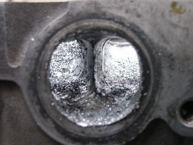
The exhaust port looked like this:
![Image]()
Normal practise with naturally aspirated engines suggests that you leave the port a smaller diameter than the exhaust manifold branch it will flow into, to prevent flow reversion. This is generally good advice, unless you really know otherwise from experience with certain cams or you're building a super-screamer and don't care about torque spread, only HORRRRRSEPOWWWWER.
This head was for a pressure charged engine that was going to go around a track as a toy, and a close coupled turbocharger generally destroys both the good and bad waves in the exhaust flow so I decided to match the ports due to the exhaust design being nozzled (that's for another day) into the collector before the turbo.
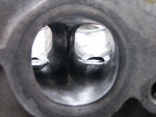
With this in mind I attacked it with a die grinder,
![Image]()
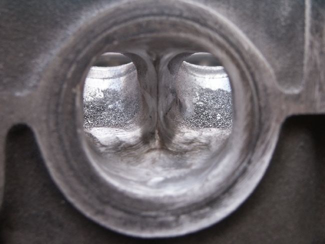
then a barrage of smaller tools
![Image]()
Then started the smoothing process
![Image]()
With the ports finally smoothed out I moved to the combustion chamber (the above was not the last polish, you can see that in the last picture)
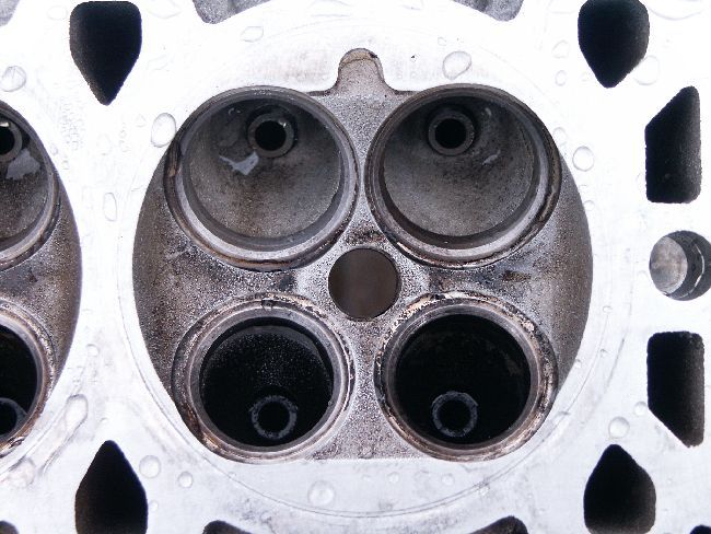
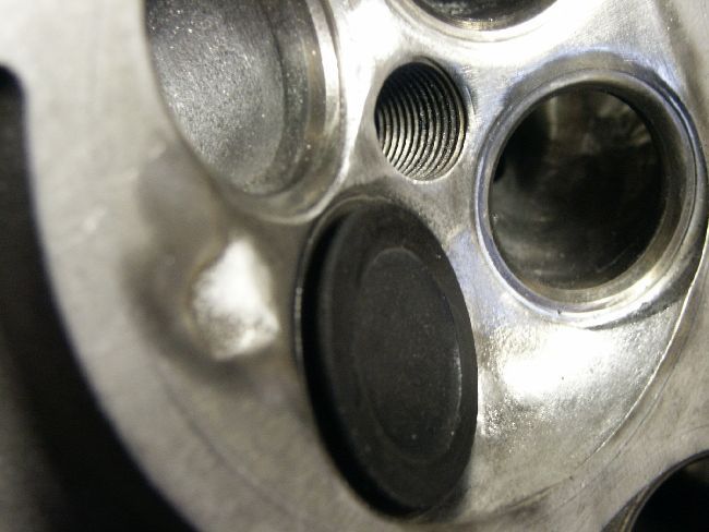
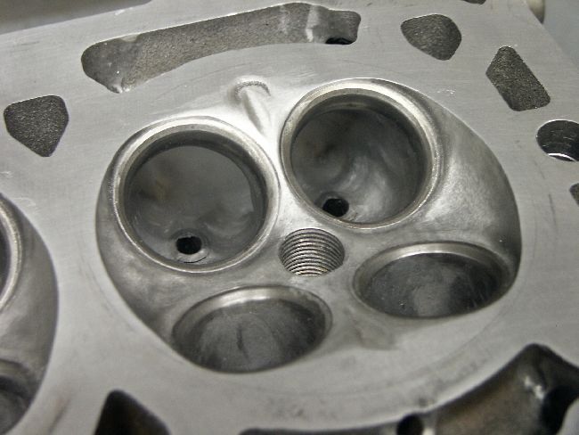
The standard chambers looked like this:
![Image]()
![Image]()
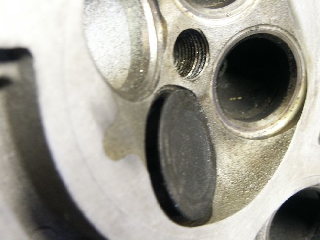
This image shows the machining that Rover did around the valves to make the 143 into the 160 (plus other things) and is included purely for interest
![Image]()
and this is what low valve lift would look like, and hence how the pocketing helps:
![Image]()
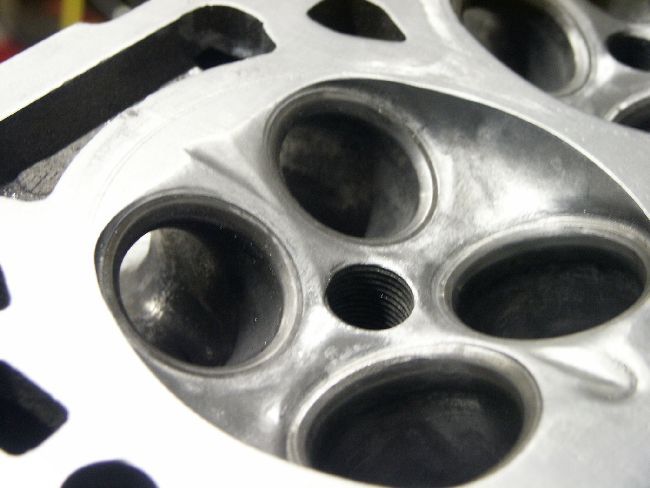
and here is a polished up chamber for comparison. The pocket machining has been fully radiused out and blended all the way up to the spark plug hole. Officinados will see an abused squish lip - oh no!
![Image]()
In a former life I was an engine researcher for companies that you may have heard of, and did all manner of good and stupid things on cylinder heads which were perched on a quartz glass cylinder so we could watch combustion take place, fuel atomisation, turbulence, swirl, tumble and squish and other things.
So with this in mind I decided to use some of the last things I worked on (not with Rover, i'll add) in this head and did some measurements that I will not labour you with. One key measurement is the injection angle, which is illustrated here with a paint brush handle:
![Image]()
This shows, as some will already know, that the k-series injection strategy is over the valve towards the centre of the cylinder where it will join with the tumble to mix, before moving back up during compression, be concentrated by the squish lip, which will then present a rich mixture near the sparkplug. This then gives a good flame kernel which leads to a progressive burn. And this a key reason the K-series has a good emissions profile.
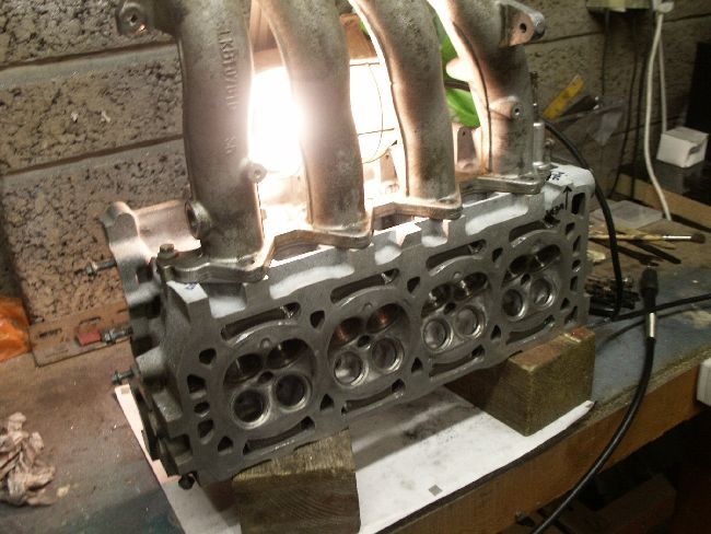
The real measurements have to be done with the the manifold on:
![Image]()
After all of that is said and done I needed to remove more metal to lower the compression ratio (CR) and wanted certain swirl characteristics that the squish lip won't lend itself to.
I would like to make it clear that I do not believe myself to be smarter than the Rover engine design team, but I was working in this area for a number of years and a number of years after Rover had finished development with all that that delivered, such as good CFD, simpler laser doppler velocimetry, and other good research and design tools, so I just wanted to use something new on an already good design.
I created opposing squish lips/jets, one straight towards the plug, and one offset to drive more swirl near TDC.
![Image]()
The offset nature of the exhaust jet can be seen here:
![Image]()
and this is the completed head, complete with hand sanded ports:
![Image]()
The head was then cleaned up, degreased, and bagged.
Sadly the man no longer wants it as he is not going ahead with his car and bought a Nissan Skyline instead, so I wont know if the squish jets worked well, whether it helped or hindered emissions or anything about it's performance.
I've ground the valves in and fitted valve stem oil seals and the spring gear and put it back in it's bag.
I'd cry, but I was paid.
The head was a good condition vvc 160 unit with relatively poor cast features but good guide to valve cocentricity and no scary features.
As it was going on a pressure charged engine I decided to go to town on the ports and combustion chamber, match the manifolds, both inlet and exhaust (sometimes controversial), but to watch my hotspots and leave metal to transfer heat away from the valves.
The head started like this:
The first job I attended to was to clean up the water passages. I do not have photos of this, but they look good now.
The second job was to clean up the casting near the VVC hydraulic control unit (HCU) rack
This photo shows the HCU rack boss after the casting flash had been removed:
I then radiused the cam ladder oilways that flow around the ladder bolts as the passages are quite narrow and you don't want to lose unnecessary oil pressure to the cam bearings. If you don't quite follow then think of a bellmouth and how it prevents losses to turbulence and recirculation.
The first picture shoes standard and the second after radiusing -
I then used rotary sanding tools to clean up the coolant passage elbow, and thought that the Magpies would like something shiny, so I cleaned off the surface corrosion
I use a Makita die grinder (240v) with a home-made variable speed control for heavy cuts and large diameters, but I also use these kinds of tools when I have a nice soft aluminium head to alter, especially for combustion chambers:
These are the inlet ports, as viewed from the manifold.
You can see quite a high surface roughness, a rather nasty casting line on the web between the ports, the seats are not well aligned with the port walls, and the web is quite thick leading to a rather blunt bifrucation into each valve from the port entrance.
The was simply cleaned up, the shape of the valve guide bosses were smoothed out but not completely removed as it uses a cut down valve stem guide and I wanted to retain some metal to dump heat to. Conventional wisdom suggests that the valve guide boss should be removed to prevent a partial throat in the port, and I also take that view, but in a forced induction engine I like so metal to take up excess transferred heat from the inevitable too-much-boost so it was a compromise.
The bifrucation was taken down to a knife edge with a little special thing done to it, so that's why there no pictures.
The exhaust port looked like this:
Normal practise with naturally aspirated engines suggests that you leave the port a smaller diameter than the exhaust manifold branch it will flow into, to prevent flow reversion. This is generally good advice, unless you really know otherwise from experience with certain cams or you're building a super-screamer and don't care about torque spread, only HORRRRRSEPOWWWWER.
This head was for a pressure charged engine that was going to go around a track as a toy, and a close coupled turbocharger generally destroys both the good and bad waves in the exhaust flow so I decided to match the ports due to the exhaust design being nozzled (that's for another day) into the collector before the turbo.
With this in mind I attacked it with a die grinder,
then a barrage of smaller tools
Then started the smoothing process
With the ports finally smoothed out I moved to the combustion chamber (the above was not the last polish, you can see that in the last picture)
The standard chambers looked like this:
This image shows the machining that Rover did around the valves to make the 143 into the 160 (plus other things) and is included purely for interest
and this is what low valve lift would look like, and hence how the pocketing helps:
and here is a polished up chamber for comparison. The pocket machining has been fully radiused out and blended all the way up to the spark plug hole. Officinados will see an abused squish lip - oh no!
In a former life I was an engine researcher for companies that you may have heard of, and did all manner of good and stupid things on cylinder heads which were perched on a quartz glass cylinder so we could watch combustion take place, fuel atomisation, turbulence, swirl, tumble and squish and other things.
So with this in mind I decided to use some of the last things I worked on (not with Rover, i'll add) in this head and did some measurements that I will not labour you with. One key measurement is the injection angle, which is illustrated here with a paint brush handle:
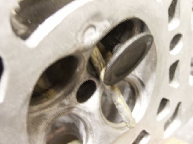
This shows, as some will already know, that the k-series injection strategy is over the valve towards the centre of the cylinder where it will join with the tumble to mix, before moving back up during compression, be concentrated by the squish lip, which will then present a rich mixture near the sparkplug. This then gives a good flame kernel which leads to a progressive burn. And this a key reason the K-series has a good emissions profile.
The real measurements have to be done with the the manifold on:
After all of that is said and done I needed to remove more metal to lower the compression ratio (CR) and wanted certain swirl characteristics that the squish lip won't lend itself to.
I would like to make it clear that I do not believe myself to be smarter than the Rover engine design team, but I was working in this area for a number of years and a number of years after Rover had finished development with all that that delivered, such as good CFD, simpler laser doppler velocimetry, and other good research and design tools, so I just wanted to use something new on an already good design.
I created opposing squish lips/jets, one straight towards the plug, and one offset to drive more swirl near TDC.
The offset nature of the exhaust jet can be seen here:
and this is the completed head, complete with hand sanded ports:
The head was then cleaned up, degreased, and bagged.
Sadly the man no longer wants it as he is not going ahead with his car and bought a Nissan Skyline instead, so I wont know if the squish jets worked well, whether it helped or hindered emissions or anything about it's performance.
I've ground the valves in and fitted valve stem oil seals and the spring gear and put it back in it's bag.
I'd cry, but I was paid.
") You have a huge knowledge, especially when you provide technical description and answers people normally ask on here...Are you an engineer?
You have a huge knowledge, especially when you provide technical description and answers people normally ask on here...Are you an engineer?

